Configuring PPP

This chapter describes how to configure the Point-to-Point Protocol (PPP) on serial ports on
Cisco 1000 Series Connected Grid Routers (hereafter referred to as the Cisco CG-OS router or
CGR 1000).

PPP over the serial port provides IP connectivity to downstream systems within the Supervisory Control and Data Acquisition (SCADA) system.
Additionally, this chapter provides details on enabling and configuring serial ports with either a RS232 DCE or RS485 interface.
This chapter includes the following sections:

Information About PPP

PPP over the serial port provides IP connectivity to downstream systems within the SCADA system.
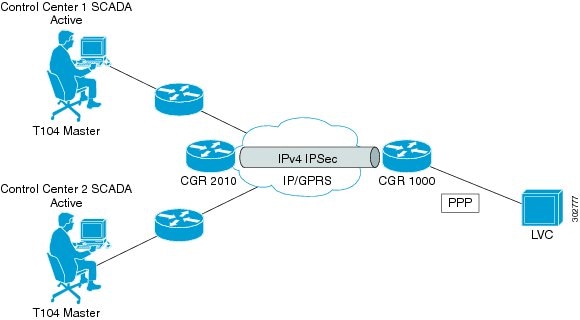
Figure 2-1 provides an example in which you enable the serial port on a CGR 1000 and configure PPP encapsulation on that port to provide connectivity to a low voltage concentrator (LVC). Data from the LVC is then transmitted over a secure IPSec tunnel network to a Control Center for processing.
Challenge Handshake Authentication Protocol (CHAP) provides authentication for communications between the LVC and the CGR 1000. With CHAP, the secret must be in plaintext form. However, the router also supports encrypted passwords.
Figure 2-1 CGR 1000 Serial Port Configured with PPP Encapsulation Provides IP Connectivity within SCADA System

Prerequisites

See the Before You Begin sections below.

Guidelines and Limitations

Verify that the serial port is not configured with another encapsulation method before configuring the serial port for PPP encapsulation by entering the show interface serial slot/port command.

Default Settings

Table 2-1 lists the default settings for the serial ports, line, and PPP parameters.
Table 2-1 Default Settings for Serial Port and PPP 
Parameter
Default
Serial port
Disabled
Media type: RS232
Frame size: 100 bytes
Maximum Idle: 10 ms
Pulse time: 500 ms
Full-duplex
Line
Data bits: 8
Flow control: None
Parity: None
Speed: 9600
Stop bits: 1
PPP
Disabled
CHAP authentication: Disabled
Restart delay: 30 seconds

Enabling the CGR 1000 Serial Port

You can configure the two serial ports on the Cisco CG-OS routers to operate as either a RS232 or RS485 interface to provide IP connectivity to systems within the SCADA system.
For hardware details on the serial ports, see the Cisco 1120 and 1240 Hardware Installation Guides.

BEFORE YOU BEGIN

Determine availability of serial port on the Cisco CG-OS router.

DETAILED STEPS

 
Command
Purpose
Step 1 
configure terminal
Router enters the global configuration mode.
Step 1 
interface serialslot/port
Enters the interface command mode for the serial slot/port.
Note The slot/port configuration for the serial port can be 1/1 or 1/2.
Step 2 
descriptiontext
Provides a textual description of the interface being configured.
text-Allows 80 alphanumeric, case sensitive, characters.
Step 3 
ip addressip address mask[secondary]
Specifies a primary or secondary IPv4 address for an interface.
ip address mask-The network mask can be a four-part dotted decimal address. For example, 255.0.0.0 indicates that each bit equal to 1 means the corresponding address bit belongs to the network address.
The network mask can be indicated as a slash (/) and a number (a prefix length). The prefix length is a decimal value that indicates how many of the high-order contiguous bits of the address comprise the prefix (the network portion of the address). A slash must precede the decimal value and there is no space between the IP address and the slash.
Step 4 
no shutdown
Brings up the port, administratively.
Step 5 
media-type {rs232 | rs485}
Specifies the media type on the serial port. RS232 is the default.
Step 6 
frame-sizenumber
Sets the maximum bytes per frame.
number-Values of 1 to 512. Default setting is 100 bytes.
Step 7 
max-idlenumber
Sets the gap between frames.
number-Value of 1 to 1000. Default setting is 10 ms.
Step 8 
pulse-timenumber
Defines the period of time before the software notifies a connecting system of an up or down state (enabled/disabled) of the serial port or its link.
number-Value of 1 to 3000. Default setting is 500 ms.
Step 9 
{full-duplex | half-duplex}
Configures the serial port to operate in either full-duplex or half-duplex mode. Default setting is full-duplex.
Step 10 
copy running-config startup-config
(Optional) Saves this configuration change.

EXAMPLE

This example shows how to enable serial port interface 1/1 on the router, define that interface as a RS232 media-type, enable PPP encapsulation on the interface, and add a description.
router# configure terminal 
router(config)# interface serial 1/1
router (config-if)# encapsulation ppp
router (config-if)# media-type RS232
router (config-if)# no shutdown
router (config-if)# description "Adding PPP encapsulation to serial port"

Clearing Interface Counters

When debugging a connection issue, you can use any of all of the following commands to clear the counters.
Command
Purpose
clear counters interface all
Clears counters on all interfaces.
clear counters interface serial slot/port
Clears all interface counters for a specified interface.

Configuring the Line Parameters

You can set and modify the line parameters using the Linux TTY application for each of the Cisco serial ports on the CG-OS router.

BEFORE YOU BEGIN

Enable the serial port on the CG-OS router and define the interface as a RS232 or RS485.

DETAILED STEPS

 
Command
Purpose
Step 1 
configure terminal
Router enters the global configuration mode.
Step 1 
line tty {1 | 2}
Enter this command at the global configuration mode to modify line settings.
1-Configures the line for serial port 1/1
2-Configures the line for serial port 1/2
Step 2 
[no] databits
Defines the number of data bits per character.
number-Values are 5 to 8. Default values is 8.
The no form of the command disables the function.
Step 3 
[no] flowcontrol {hardware | none}
Enables or disables the use of flow control on the line.
hardware-Enables CTS and RTS as the flow control mechanism.
none-Select this option when the configuration does not want or require flow control.
The no form of the command disables the function.
Note Setting must match that of the peer.
Step 4 
[no] parity {even | odd | none}
Sets or disables the terminal parity.
Note Setting must match that of the peer
Step 5 
[no] speed value
Sets the transmit and receive speeds for the line.
Value-Any value between 300 and 115200 baud rate. Default value is 9600.
The no form of the command removes the setting.
Note Setting must match that of the peer.
Step 6 
[no] stopbits {1 | 2}
Defines the asynchronous line stop bits. Default value is 1.
Note When you set the stop bits for a value of 2 and the data bits for a value of 5, the stop bits setting becomes 1.5
Step 7 
[no] location string
Specifies the location of the router.
string-Up to 240 bytes.

EXAMPLE

This example shows how to configure line settings on serial port 1/2.
router# configure terminal 
router(config)# line tty 1
router (config-line)# flowcontrol none
router (config-line)# parity even
router (config-line)# speed 56000

Enabling PPP

You must enable the PPP feature on the Cisco CG-OS router. It is not enabled by default.

DETAILED STEPS

 
Command
Purpose
Step 1 
configure terminal
Enters the global configuration mode.
Step 2 
feature ppp
Enables the PPP feature.

EXAMPLE

This example shows how to enable PPP on the CG-OS router.
router# configure terminal 
router(config)# feature ppp

Configuring PPP

You can configure one or both of the CGR 1000 serial ports to run PPP.

BEFORE YOU BEGIN

Enable the serial port on the CG-OS router and define the interface as a RS232 or RS485. See Enabling the CGR 1000 Serial Port.
Enable PPP on the CG-OS router. See Enabling PPP.

DETAILED STEPS

 
Command
Purpose
Step 1 
configure terminal
Enters the global configuration mode.
Step 1 
(Optional) feature password encryption aes
Enables AES encryption on a system level.
Note Only required when configuring a type 6 password in Step 7.
Step 2 
(Optional) key config-key ascii
Adds or modifies the master key at the system level.
After entering this command, you are prompted for the master key.
Note Only required when configuring a type 6 password in Step 7.
Step 3 
interface serial slot/port
Enters the interface command mode for the serial slot/port.
slot/port-The slot/port configuration for the serial port can be 1/1 or 1/2
Step 4 
encapsulation ppp
Enables PPP encapsulation on the serial port.
Step 5 
[no] ppp authentication chap [callin]
Enables CHAP authentication on the serial port as either a server or client.
callin-Enter this option to provide authentication as a client.
By default, not entering the command option, callin, provides authentication as a server.
Note Enter the no form of this command to disable authentication.
Step 6 
ppp chap hostname name
Defines a hostname for PPP CHAP authentication.
Step 7 
ppp username s1 passwd {0s2 | 6 type6pwd | 7type7pwd}
Defines the password in plain text or as encrypted (type 6 or 7).
Encrypted passwords must be copied and pasted from another session.
s1- Name of the PPP peer (the downstream device to which the router connects).
s2-PPP password in plain text.
6-Encrypted AES password.
7-Scrambled password.
Step 8 
(Optional) ppp peer-addressip-addr
Provides an IP address to the peer.
Enter an IP address when the peer requires an address from the Cisco CG-OS router for IPCP negotiation.
ipaddr-IPv4 address for the peer (format: x.x.x.x)
Step 9 
ppp restart-delay delay
Sets the delay interval that the router waits before attempting to restart protocol negotiation with the PPP peer after a disconnect.
delay-Values range from 5 to 86400 seconds. Default value is 30.
Note A PPP peer might disconnect after completion of a successful PPP link.

EXAMPLE

This example shows how to configure PPP (as a server) with encrypted authentication of type 6 on the enabled serial port 1/1.
router# configure terminal 
router(config)# interface serial 1/1
router(config-if)# encapuslation ppp
router(config-if)# ppp authentication chap callin
router(config-if)# ppp chap hostname cgr1120
router(config-if)# ppp username lcv-va07 passwd 0 secretword

Verifying Configuration

To display PPP or serial port configuration information, perform one of the following tasks.
Command
Purpose
show interface
Displays configuration details for all interfaces on the router.
show interface serial slot/port
Displays configuration for a specific serial port.
Note When you enable PPP encapsulation on the serial interface, the interface only appears as up after successful PPP negotiation.
show line
Displays all configuration information for the line.
show line tty {1 |2}
Displays the line settings for the specified serial port.

Configuration Examples

router# configure terminal 
router(config)# interface serial 1/1
router(config-if)# media-type RS232
router(config-if)# no shutdown
router(config-if)# exit
router(config)# line tty 1
router (config-line)# flowcontrol none
router (config-line)# parity even
router (config-line)# speed 56000
router (config-line)# exit
router (config)# exit
router (config-if)# description "Adding PPP encapsulation to serial port"
router(config-if)# encapuslation ppp
router(config-if)# ppp authentication chap callin
router(config-if)# ppp chap hostname cgr1120
router(config-if)# ppp username lcv-va07 passwd 0 secretword
router (config-if)# copy running-config startup-config

Feature History


Feature Name
Release
Feature Information
Active serial ports on CGR 1000 routers.
Cisco CG-OS Release CG2(1)
Initial support of the feature on the CGR 1000 Series Routers.
PPP over serial ports.
Configuring PPP Rating: 4.5 Diposkan Oleh: Unknown

No comments:

Post a Comment